The LEDs can be flashed i various ways.
You can set them using the traditional 555 and 4017 ICs or you can just use a
microprocessor chip. The traditional way uses a lot of components, is bulky and
not only that, offers limited "straight" LED falshing sequence. The
microprocessor on the other hand, not only offers unlimited LED flashing
sequence and also, timing but I saves a lot of space. You only need one IC chip
and some resistors. However, in order to get to this stage, you would have to
invest in a microprocessor programmer and also spend some time learning the
programming language. Since I was always short of time, I used a short cut.
Heh.
And one very good thing about using the
microprocessor is that it can be used on various voltage range, from 3 volts to
a maximum of 5 volts. Which, in this case, is ideal because the toy Tricorder
uses two 'AAA' batteries which means, 3 volts. Since this is a straighforward
circuit, all I have to do is to calculate out the current required for the LEDs
and then concentrate on the flashing sequence. The sequece I had in mind was
something similar to the "scanning" sequence from the TNG and Voyager Tricorders
but with some variation patterns. This idea came to me when I was playing with
the toy; the moment the Tricorder's flap was opened, all the LEDs would light up
for about one second. And during this time, the two buttons would not respond.
So, I take it, this is the Tricorder's Startup sequence, like when you first
switch on your computer.
And so, the LED sequence start like
this, when it is first activated, within the one second window, the yellow LEDs
would sweep from left to right and back again. Then the blue LEDs would do the
same. After the one second window has passed, the yellow LEDs would start
scanning followed by the blue. They would scan in normal mode for five passes
before doing a special two pass scan. After that, it would go back to normal
scan and the whole cycle repeats itself indefinitely.
This is the circuit which I drew in a hurry as
I do not have a proper software to do them justice. And as you can see,
there are no electronic symbols there, just the connections. Oh, darn! I
forgot to put in the values of the current limiting resistors as well. You
only need them for the yellow part of the LEDs. I should have done the
same for the green LEDs but its too late for that now.
And this is the circuit in prototype stage. I
tend to use these boards a lot as they're quite useful when I want to test
a circuit or change things in a hurry. Not only that, these prototype
boards can be linked to form a larger board. But do not drop them as the
heavier electronic components tend to drop out. Also, invest in a good
wire stripper as well. Trust me, you're going to need it.
This is
the video of the prototype
THE CIRCUIT BOARD
The next stage for the circuit is
to transfer it form the prototype stage to the actual circuit board. Because
this is just a one-off circuit, there is no point in designing a proper circuit board
and have it professionally made. Moreover, not many here would entertain
requests for a single PCB unless you do not mind paying a premium for it. And
so, because its a simple circuit, I would just go for a simple stripboard (or
breadboard). But if I want to use SMT components, then the stripboard idea has to
be abandoned. It has to use a proper PCB design. I can etch the board by
myself but the time and money to invest in such is just not worth it. I'll
tell you why.
First, you have to have a PCB pattern or artwork made out.
You can do this either with a simple etch-resist pen and draw it on the PCB.
However, this method only allows you to etch one single board and if you
need another board, you have to draw the design on the board again. But if you're
thinking of doing more than one board in one go, you can get a proper software
to create the PCB artwork, get it printed out and turn it into a transparent
positive film (but you have to use a special PCB which is very expensive).
There are other ways to make sure your design is tranferred to the board
but here, the two methods above are the most common. Once you have transferred
the artwork on to the board, you can begin etching the PCB. And one thing about
the chemicals is that its awful. Ferric Chloride leaves a very bad stain on
any surface. During the etching, you would have to agitate the bath and also
make sure its slightly hot to speed up the etching process. Once, I was about
to build an etching tank but then, I realised the problems of disposing the
used chemicals is just not worth it. And in the last stage, which is the most
tedious of all, is to start drilling the holes in the PCB. If you're using
fibreglass PCBs, you'd have to buy a really good hi-speed drill and those expensive
and fragile tungsten drill bits which snap-off very often. With a nornal drill bit,
it would go blunt in less than three holes for a fibreglass PCB
board.
I have cut out the stripboard exactly to the
size that can be fitted into the toy. But if I were to use SMD components,
the actual PCB, I believe, would be half the size. Still, this is a
prototype and so, the choice of PCB design/material is not going to make
any difference.
There are many types of stripboards available
but I always buy the strip ones. For this project, I looked for the same
design but, with the solder mask. The mask is to make sure the solder
stays in one place. This will minimise unwanted solders between
tracks or bunching up together. Although you see are holes here, but if
you look carefully, you will notice they are actually long strips. Notice
the five solder joints where the solder does not flow
everywhere.
TOOLS OF THE
TRADE
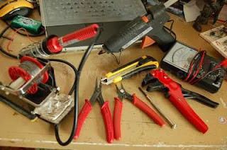
This were the tools I used for the
project. The only ones not shown were the double-sided tapes and the cheap
rotary tool. (Clockwise from Left) My trusty 25 Watt soldering iron with a
holder and a generous roll of non-ROHS solder which took me more than 10
years to go through, a hot glue gun, a multimeter, a T-Rex wire stripper,
small screwdriver, a sharp wire cutter, a pair of long nose pliers
and a blade.
OK. let's
take a break before continuing. As usual, when I do something, I always find that
I never do have the
proper tools at hand. Sometimes, its good because it forces me
to improvise. Sometimes its bad because while looking for a replacement, many things can happen
from breaking something to losing a part to delaying the project. Not only
that, coupled with my impatience and having the best hand-eye coordination, the project
would be destroyed in the shortest time possible. Still, at the end
of the day, I wished for a full complement of tools and most importantly, a place/room for all this.
As you can see in the picture above, these are the minimum set of tools
I used for this project.
OK, OK.
These are the only tools I could find and own at the moment.
The rest, I try to improvise. (Its amazing what you can do
with minimum tools, such as a jeweller's screwdriver which can double as a drill too. Or a
cutter which can be used to tighten nuts and then become a pair of pliers
after it has gone blunt.)
Because I am doing the electronics
here, the most important tool of all is the soldering iron, followed by
the multimeter. I actually have two meters, one analogue and one digital. The
analogue meter is very important when you want to detect voltage changes.
And not only that, it can give the right amount of current when I need to test a
LED. However, if I wanted an accurate reading of the voltage or resistor, I will
pull out the digital multimeter instead.